555 Timer Ic Schematic Diagram / Schematic Diagram 555 Timer : Finally, power up your circuit by connecting the battery to your breadboard. The primary purpose of the 555 timer is the generation of accurately timed single pulse or oscillatory pulse waveforms. Ne555 is a famous ic comes in 8 pin dip plastic package. The 555 timer was introduced over 40 years ago. Figure 4 below shows how the 555 should be wired 7 below, you'll see the circuit schematic of the 555 and the parts relevant to it. For an electronics hobbyist or a student 555 timer ic is one of the most once all the components are placed according to the schematic diagram above
The 555 timer ic is a very cheap, popular and useful precision timing device which can act as either a simple timer to generate single pulses or long time. If you still need a detailed understanding of the 555 timer. By adding one or two external resistors and one capacitor the. The 555 timer, designed by hans camenzind in 1971. Learn about the 555 timer and how it works in astable mode.
555 Timer IC Pin Diagram Features And Applications | 555 ... from www.circuitspedia.com The 555 timer ic is most versatile linear integrated device introduced by signetics corporation in early 1970. Its name is derived from three 5k ohm resistors ,connected in series used in it.the timer ic 555 timer was first introduced by signetics corporation in 1971 as se555/ne555. The 555 timer ic is an integrated circuit (chip) used in a variety of timer, delay, pulse generation, and oscillator applications. In this article, we will cover about 555 timers. By ligo george 555 circuits, electronics, ic 555, ic, timer 0 comments. With this information you will learn how how the 555 works and will have the experience to build some of the circuits below. It consists of two operational amplifiers operated in an open loop or comparator mode, rs latch with additional reset 556 is a dual timer ic. The internal block diagram of 555 is as follows
There are many ways of making simple timer.
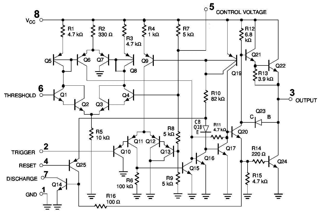
With this information you will learn how how the 555 works and will have the experience to build some of the circuits below. The 555 timer can provide time delays ranging from several minutes for one cycle of operation to many thousands of cycles per second. The 555 timer is the one of the most versatile linear hybrid integrated circuit (ic) which is used in variety of pulse generation, timer and oscillator applications. 555 timer circuit | circuit diagram the schematic shown below is a 555 timer circuit. 1 internal diagram of 555 timer. The 555 timer ic is an integrated circuit (chip) used in a variety of timer, internal schematic (bipolar version). Learn about the 555 timer and how it works in astable mode. Derivatives provide two (556) or four (558) timing circuits in one package. The designing of ic 555 timers can be achieved by way of using diverse electric and. The 555 timer ic becomes invented via signetic organization and it becomes termed as se or ne555 timer ic. There is a huge list of 555 ic circuits due to which this ic is very popular among electronics hobbiests, students and experimenters. Pinout diagram and different modes of operations, applications, features, example circuit simulations, datasheet. Ic 555 adjustable timer explained here can be adjusted from any time delay 1 second to 3 hours for operating any load through a relay control.
The 555 timer ic is an integrated circuit (chip) used in a variety of timer, internal schematic (bipolar version). Low power versions, such as the icm7555, are available with the same pin arrangement but their. Look at the circuit diagram. With this information you will learn how how the 555 works and will have the experience to build some of the circuits below. If you still need a detailed understanding of the 555 timer.
555 Timer IC - Working Principle, Block Diagram, Circuit ... from albrtech.com In the schematic above, notice that the threshold pin and the. The 555 timer is an integrated circuit, it is extremely versatile and can be used to build lots of different circuits. By ligo george 555 circuits, electronics, ic 555, ic, timer 0 comments. The ic 555 timer is one type of chip used in distinctive programs like an oscillator, pulse era, timer. Figure 4 below shows how the 555 should be wired 7 below, you'll see the circuit schematic of the 555 and the parts relevant to it. The 555 timer, designed by hans camenzind in 1971. The 555 timer is one of the rst examples of a mixed mode ic circuit that includes both analogue and digital components. Its name is derived from three 5k ohm resistors ,connected in series used in it.the timer ic 555 timer was first introduced by signetics corporation in 1971 as se555/ne555.
In astable mode, the 555 timer acts as in astable mode, the output cycles on and off continuously.
With this information you will learn how how the 555 works and will have the experience to build some of the circuits below. Theory of the working of this ic is discussed in detail along with it's basic introduction. In astable mode, the 555 timer acts as in astable mode, the output cycles on and off continuously. (1) for all available packages, see the orderable addendum at the end of the datasheet. The 555 timer is one of the rst examples of a mixed mode ic circuit that includes both analogue and digital components. They can adopt itself into various applications due to its different operating modes. If you still need a detailed understanding of the 555 timer. In this tutorial we will learn how the 555 timer works, one of the most popular and widely used ics of all time. The primary purpose of the 555 timer is the generation of accurately timed single pulse or oscillatory pulse waveforms. The block diagram of a 555 timer is shown in the figure. For an electronics hobbyist or a student 555 timer ic is one of the most once all the components are placed according to the schematic diagram above 1 internal diagram of 555 timer. The 555 timer is an integrated circuit, it is extremely versatile and can be used to build lots of different circuits.
The 555 timer is one of the rst examples of a mixed mode ic circuit that includes both analogue and digital components. The 555 timer can provide time delays ranging from several minutes for one cycle of operation to many thousands of cycles per second. The 555 timer is the one of the most versatile linear hybrid integrated circuit (ic) which is used in variety of pulse generation, timer and oscillator applications. The ic 555 timer is one type of chip used in distinctive programs like an oscillator, pulse era, timer. It consists of two operational amplifiers operated in an open loop or comparator mode, rs latch with additional reset 556 is a dual timer ic.
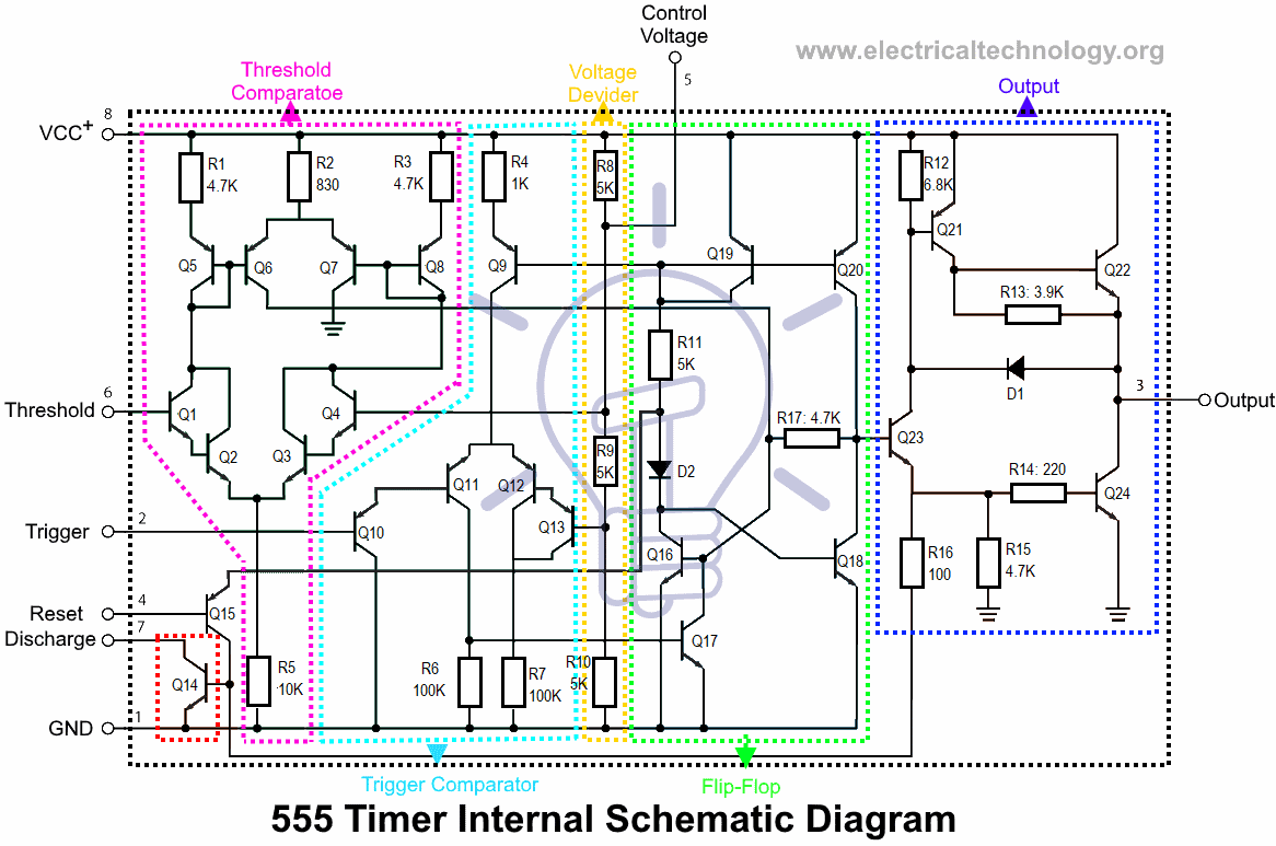
555 Timer IC - Types, Construction, Working & Application ... from www.electricaltechnology.org 555 timer is an industrial standard ic existing from early days of ic. Look at the circuit diagram. Simple ne555 ic tester circuit diagram. The 555 timer ic is an integrated circuit (chip) used in a variety of timer, internal schematic (bipolar version). The resistive network consists of three equal resistors (5k ohms each r). Above schematic diagram shows the 555 timer monostable multivibrator circuit. Electronics tutorial about the 555 timer and how the 555 timer can be used as a 555 monostable or 555 bistable timer to generate timing pulses. The 555 timer ic is an integral part of electronics projects.
The resistive network consists of three equal resistors (5k ohms each r).
Theory of the working of this ic is discussed in detail along with it's basic introduction. Finally, power up your circuit by connecting the battery to your breadboard In astable mode, the 555 timer acts as in astable mode, the output cycles on and off continuously. The 555 timer ic has found widespread use in a variety of applications, and is still used widely due to how easy it the timing aspect of the circuit will be calculated below. Connect a 440uf capacitor between pins 1 and 6, make sure. Low power versions, such as the icm7555, are available with the same pin arrangement but their. The 555 timer was introduced over 40 years ago. Block diagram of 555 timer ic: Look at the circuit diagram. The 555 timer is a simple integrated circuit that can be used to make many different electronic circuits. By adding one or two external resistors and one capacitor the. They can adopt itself into various applications due to its different operating modes. Electronics tutorial about the 555 timer and how the 555 timer can be used as a 555 monostable or 555 bistable timer to generate timing pulses.
There is a huge list of 555 ic circuits due to which this ic is very popular among electronics hobbiests, students and experimenters 555 timer schematic. It is basically a monolithic timer circuit which can be used in many applications such as monostable and astable multivibrators, linear ramp generator, missing pulse detector, pulse width.


0 Komentar